Complete reference for ECE/MAE 148 — covering Docker environment setup, X11 display forwarding, OAK-D camera calibration, VESC motor tuning, PID controller configuration, and custom ROS2 node development.
🍓Raspberry Pi 5
🐳Docker
🤖ROS2 Foxy
01
Initial Setup & Docker Installation
Prepare the Raspberry Pi with a clean, reproducible Docker environment
Docker allows the entire Robocar software stack — ROS2, camera drivers, motor controllers, and all Python dependencies — to run inside a self-contained container. This means the host Raspberry Pi operating system stays clean, every student robot runs identical software, and a broken environment can always be restored by re-pulling the Docker image rather than reinstalling the entire OS.
1
SSH into Your Pi
Replace XX with your robot's assigned number. The .local suffix uses mDNS (Bonjour/Avahi) to locate the Pi on your local network without needing to know its IP address.
Terminal — your laptop
ssh pi@ucsdrobocar-148-XX.local
2
Remove Old Docker Versions
Removes any conflicting legacy packages that could cause dependency conflicts during the official Docker installation. "Package not found" messages are completely normal — they simply mean these packages were never installed.
ca-certificates enables verification of HTTPS connections. curl downloads files from the web. gnupg verifies Docker's cryptographic signature to confirm that the packages you install are authentic and unmodified.
Adding your user to the docker group lets you run docker without typing sudo every time. A full reboot is required — the group membership change only takes effect after starting a new login session.
Pi terminal
sudo usermod-aG docker $USER
sudo reboot
7
Verify Installation
SSH back in after the reboot and confirm Docker is working correctly.
Pi terminal (after reboot)
docker --version# Should print a version numberdocker run hello-world # Should print "Hello from Docker!"groups $USER | grep docker # Should show "docker" in the list
✓
Success
You should see "Hello from Docker!" in the output. If you see permission denied, fully log out of your SSH session and reconnect — the group change requires a fresh login.
02
Pulling the Robocar Image
Download the pre-built UCSD Robocar software environment (~14.7 GB)
The Robocar Docker image contains a fully configured environment including ROS2, OAK-D depth camera drivers (DepthAI), VESC motor controller drivers, all lane detection packages, and every required Python dependency. You pull it once and it persists on the Pi's storage.
⚠
Network Warning — Use Home Wi-Fi or Wired Ethernet
This image is approximately 14.7 GB. The campus Wi-Fi network frequently drops connections mid-download, corrupting the image and forcing a full re-pull. Use a home network or a wired Ethernet connection. If the download is interrupted, simply re-run the pull command — Docker automatically resumes from the last successfully downloaded layer.
Pi terminal — expect 20–40 minutes on a fast connection
Re-run docker pull — it resumes automatically from the last completed layer
"No space left on device"
Run docker system prune -f to remove old images and stopped containers
Image shows a size of 0B
The pull failed silently. Delete with docker rmi ghcr.io/ucsd-ecemae-148/ucsd_robocar:stable and re-pull
Authentication error
The image is public. Verify your internet connection: ping 8.8.8.8
03
Graphical Interface Setup (X11 Forwarding)
Stream GUI windows from the Pi to your laptop screen over SSH
Enhanced
X11 forwarding lets programs running on the Pi render graphical windows (calibration sliders, live camera feeds, debug overlays) and stream those windows over your SSH connection to your laptop's screen. Without X11 forwarding, none of the visual calibration tools will work.
ℹ
Complete This Section Before Creating the Docker Container
Set up X11 forwarding on both your laptop (Steps 2–3) and the Pi host (Steps 1 and 4) now. You will verify that it works inside the Docker container in Section 4, after the container is created.
Step 1 — Install X11 Apps on the Pi
Pi terminal
sudo apt updatesudo apt install-y x11-apps
Step 2 — Install an X Server on Your Laptop
Your OS
Software to Install
Required Extra Step
macOS
XQuartz — download from xquartz.org
After installing, open XQuartz → Preferences → Security tab → check "Allow connections from network clients". Then fully restart your Mac.
Windows
MobaXterm — download from mobaxterm.mobatek.net
No extra steps needed. MobaXterm includes a built-in X server and handles X11 forwarding automatically.
Linux
X11 is built into all major distributions
No extra steps needed.
Step 3 — Connect via SSH with Forwarding Enabled
The -Y flag enables "trusted" X11 forwarding, which is required when the Docker container runs as root. The stricter -X flag blocks cross-user connections and will prevent calibration windows from opening inside Docker.
Your laptop terminal
# Use -Y (trusted forwarding) — required for the Docker containerssh-Y pi@ucsdrobocar-148-XX.local
# Alternatively, -X (untrusted forwarding) — use only if -Y is unavailablessh-X pi@ucsdrobocar-148-XX.local
Step 4 — Test X11 on the Pi Host (Before Docker)
Pi terminal — NOT inside Docker
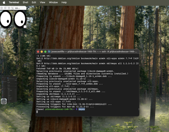
xeyes# A pair of animated eyes should appear on YOUR LAPTOP SCREEN# The eyes follow your mouse cursor. Press Ctrl+C to close.
Fig 3.1 Successful X11 host test — the xeyes window appears on your laptop, forwarded from the Pi over SSH.
✓
xeyes Opens? You're Ready for Section 4
If xeyes appeared on your laptop screen, X11 forwarding is working correctly on the Pi host. Proceed to Section 4 to create your Docker container.
How the Docker Flags Enable X11 (Reference)
Docker Flag
What It Does
Without It
-e DISPLAY=$DISPLAY
Passes the Pi's X11 display socket address into the container so GUI applications know where to connect.
GUI applications crash immediately with "cannot open display".
--volume="$HOME/.Xauthority:/root/.Xauthority:rw"
Mounts the Xauthority cookie file that proves the container is permitted to use the X server.
"Authorization required, rejecting connection" — all GUI calls fail.
--net=host
The container shares the Pi's full network stack, including the X11 IPC socket.
The X11 socket is unreachable from inside the container.
Common X11 Errors & Fixes
Error Message
Fix
"cannot open display"
SSH was not started with the -Y flag. Exit and reconnect: ssh -Y pi@ucsdrobocar-148-XX.local
"No protocol specified"
Run on the Pi host: xhost +local: then retry inside Docker
"Authorization required"
The .Xauthority file is not mounted. Check the --volume flag in your docker run command.
xeyes opens on Pi host but not inside Docker
Switch from ssh -X to ssh -Y and restart the container.
macOS: nothing appears at all
Enable "Allow connections from network clients" in XQuartz Preferences → Security. Restart your Mac after changing this setting.
If you see "timeout in locking authority file", the .Xauthority file is corrupt. Delete it and start fresh: rm ~/.Xauthority && ssh -Y pi@ucsdrobocar-148-XX.local
04
Running the Docker Container
Start the Robocar environment using a reusable shell function
The full docker run command is long and prone to typos. We store it as a shell function in ~/.bashrc on the Pi so it becomes a simple one-word command.
Step 1 — Add the Shell Function to the Pi's .bashrc
Pi terminal
nano ~/.bashrc # Scroll to the bottom and paste the function below
⚠
Replace the Placeholder Values Before Saving
Replace MY_CONTAINER_NAME with a name of your choosing (e.g., robocar_team4). Replace YOUR_TEAM_ID with your team number (e.g., 4).
Paste into Pi ~/.bashrc — edit MY_CONTAINER_NAME and YOUR_TEAM_ID
The docker run command (via robocar_docker) only works the first time — it creates a brand-new container. Once you exit, the container still exists on disk but is stopped. For every future session, use docker start + docker exec as shown in Step 3.
Step 3 — Manage the Container in All Future Sessions
Pi terminal — all future sessions after the first
# Start the stopped container (run this after a reboot or after exiting)docker start MY_CONTAINER_NAME
# Open an interactive terminal inside the running containerdocker exec -it MY_CONTAINER_NAME bash
# Open ADDITIONAL terminal tabs into the SAME running containerdocker exec -it MY_CONTAINER_NAME bash
✓
Multi-Terminal Workflow
You will regularly need 3–4 concurrent terminals: one for ros2 launch, one for editing YAML config files, one for ros2 topic echo to monitor live data, and one for debugging. Open each by running docker exec -it MY_CONTAINER_NAME bash in separate SSH windows.
Step 4 — Verify X11 Works Inside the Container
Inside Docker container
# DISPLAY must not be empty — it should show a value like :10 or :11echo $DISPLAY
# xeyes must appear on YOUR LAPTOP SCREENxeyes
05
Fixing Python Errors (If Needed)
Resolve the apport_python_hook AttributeError inside the container
On some Pi setups, the Docker container throws the following error when running ROS2 commands:
Error message to watch for
AttributeError: module 'apport_python_hook' has no attribute 'install'
The path /usr/lib/python3.8/ must match the Python version inside your container. Check it with python3 --version. If it shows Python 3.10, use /usr/lib/python3.10/sitecustomize.py.
06
Package Installation & Build
Configure setup.py and compile the ROS2 workspace with colcon
ROS2 uses colcon as its build system. Before building, we update setup.py to ensure all launch files, YAML configs, and RVIZ files are correctly installed.
Step 1 — Navigate to the Package Directory
Inside Docker
cd /home/projects/ros2_ws/src/ucsd_robocar_hub2/ucsd_robocar_nav2_pkg
Step 2 — Write the Improved setup.py
Inside Docker — write improved setup.py
cat > setup.py <<'EOF'
from setuptools import setup
import os

package_name = 'ucsd_robocar_nav2_pkg'

def package_files(directory):
    paths = []
    for (path, _, filenames) in os.walk(directory):
        for f in filenames:
            paths.append(os.path.join(path, f))
    return paths

data_files = [
    ('share/ament_index/resource_index/packages', ['resource/' + package_name]),
    ('share/' + package_name, ['package.xml']),
]

for d in ['launch', 'config', 'rviz', 'urdf', 'ros_data']:
    if os.path.isdir(d):
        data_files.append((os.path.join('share', package_name, d), package_files(d)))

setup(
    name=package_name, version='0.0.0',
    packages=[package_name], data_files=data_files,
    install_requires=['setuptools'], zip_safe=True,
    maintainer='root', maintainer_email='root@todo.todo',
    description='Nav2 launch/config package for UCSD RoboCar',
    license='TODO', tests_require=['pytest'],
    entry_points={'console_scripts': []},
)
EOF
Step 3 — Build the Workspace
Inside Docker
cd /home/projects/ros2_ws
rm -rf build install log
colcon build--symlink-installsource install/setup.bash
ros2 pkg list | grep ucsd_robocar
⚠
Always Source After Every Build
Running colcon build compiles the code but does not make it available to ROS2. You must run source install/setup.bash every time after building. Section 7 creates aliases that handle this automatically.
07
Shell Aliases: source_ros2 & build_ros2
One-command shortcuts for every build and source operation
These two aliases eliminate the most common source of student mistakes: forgetting to rebuild or re-source after changing a file.
ℹ
These Aliases Go Inside the Container
Add these to /root/.bashrcinside Docker, not the Pi host's ~/.bashrc. If your ROS2 distribution is not Foxy, update the last line accordingly (e.g., replace foxy with humble).
Inside Docker — paste into ~/.bashrc
# ── Source workspace only (fast — no recompilation) ──────────────────────
alias source_ros2='source /home/projects/ros2_ws/install/setup.bash && echo "[ROS2] Workspace sourced ✓"'# ── Full build then source (use after ANY file change) ───────────────────
alias build_ros2='cd /home/projects/ros2_ws && colcon build --symlink-install && source install/setup.bash && echo "[ROS2] Build complete ✓"'# ── Source the global ROS2 base installation ──────────────────────────────
source /opt/ros/foxy/setup.bash 2>/dev/null
Activate and test
source ~/.bashrc
source_ros2# Should print: [ROS2] Workspace sourced ✓build_ros2# Should print: [ROS2] Build complete ✓
Alias
When to Use
Speed
source_ros2
Opening a new terminal into an already-built container — no recompilation, only registers packages.
~1 second
build_ros2
After any change to Python code, YAML configs, launch files, or setup.py. Always use this after edits.
30–120 seconds
08
Camera Power Fix — USB Current & Powered Hub
Fix random camera disconnects caused by insufficient USB power
✗
Very Common Lab Issue
The OAK-D camera draws up to 900 mA at peak. The Raspberry Pi's USB ports are limited to approximately 600 mA total by firmware default. This causes the camera to disconnect randomly, produce an all-black feed, or fail to appear as a USB device entirely.
sudo nano /boot/config.txt
# Add this exact line at the END of the file:max_usb_current=1sudo reboot
Solution 2 — Powered USB Hub (Most Reliable)
Component
Requirement
USB Hub
USB 3.0 hub with an external power adapter — must not be bus-powered
Hub Power Adapter
5V / 2A minimum, dedicated supply
Connection
Pi USB-A port → Powered Hub → OAK-D + VESC + other USB devices
09
Camera Isolation — Prevent Cross-Team Interference
Ensure your robot only communicates with your own team's nodes
✗
Critical Lab Issue — Read Before Starting Any Calibration
All robots running ROS2 on the same Wi-Fi network are visible to each other by default. During a lab session with 10+ teams, your calibration GUI may be receiving another team's camera feed, or your steering commands could be controlling a different robot.
The Fix — Assign Each Team a Unique ROS_DOMAIN_ID
Nodes on different Domain IDs are completely invisible to each other at the DDS network layer. Setting a unique Domain ID requires zero code changes — it is purely an environment variable. Domain ID 0 is the system default and is not safe to use in a multi-team environment.
🏷 Team Domain ID Assignments
Your team number = your Domain ID. Valid range: 1–232 (avoid 0 — it is the shared default).
Step 1 — Set ROS_DOMAIN_ID in the Docker Run Command
Pi terminal
nano ~/.bashrc
# Find the line that reads: -e ROS_DOMAIN_ID=YOUR_TEAM_ID# Change it to your team number, for example Team 4:-e ROS_DOMAIN_ID=4 \
Step 2 — Set ROS_DOMAIN_ID Persistently Inside the Container
Inside Docker — add to ~/.bashrc
nano ~/.bashrc
# Add this line (replacing 4 with your actual team number):export ROS_DOMAIN_ID=4source ~/.bashrc
Step 3 — Verify Isolation Is Active
Inside Docker
# Must print your team number — if empty, isolation is NOT activeecho $ROS_DOMAIN_ID
ros2 topic list# Verify you only see your own topicsros2 node list# Verify you only see your own nodes
✓
Quick Lab Sanity Check
Before every calibration session, run echo $ROS_DOMAIN_ID inside Docker. If it prints empty or 0, isolation is not active and your calibration may be interfering with other teams.
10
Calibration Overview & Config Files
Understand the full calibration flow before you touch a single slider
Read First
🏁
All calibration is done on the track
Every slider adjustment in Sections 11–13 must be performed with the car physically placed on the track, camera pointed at the actual yellow lane markers your car will follow. Desktop or carpet calibration will not transfer to the track.
The Two-Phase Calibration Workflow
PHASE 1
Change Nodes (Calibration Mode)
→
PHASE 1
Launch GUI on Track
→
PHASE 1
Tune HSV & Lane Sliders
→
PHASE 2
Change Nodes (Nav Mode)
→
PHASE 2
Launch Car & Tune PID
Config Files Reference
File
Controls
Full Path Inside Docker
node_config.yaml
Which ROS2 nodes are launched — calibration GUI on/off, autonomous navigation on/off. This is the first file you edit.
Every time you edit any YAML file, Python file, or launch file, you must run build_ros2 for the change to take effect. Running source_ros2 alone is not enough for YAML changes. This is the single most common student mistake.
🔁
The Workflow You Will Repeat Constantly: Edit file → build_ros2 → test → repeat
11
Step 1 — Switch to Calibration Mode
Edit node_config.yaml to enable the GUI, then build and launch on the track
Phase 1 · Start Here
Before adjusting any sliders, you must tell ROS2 which nodes to run by editing node_config.yaml. In calibration mode, the system launches the GUI sliders and camera feed but disables autonomous driving — so the car stays still while you tune. Do not skip this step or the car may drive away during calibration.
node_config.yaml — set these exact values for CALIBRATION MODE
all_components: 1
camera_nav_calibration: 1 # ✅ ENABLE — opens the calibration slider GUIsensor_visualization: 1 # Enable for LiDAR visualization (set 0 if not using LiDAR)camera_nav: 0 # ❌ DISABLE — autonomous driving must be OFF during calibration
car_config.yaml — same values for both calibration and navigation
oakd: 1 # Enable the OAK-D cameravesc_without_odom: 1 # Enable VESC motor controller (no odometry feedback needed)
Build the Workspace
After saving both config files, you must rebuild before the changes take effect:
Inside Docker
build_ros2# Wait for "Build complete ✓" — this takes 30–120 seconds
Place the Car on the Track and Launch
🚗
Go to the track now
Place your car on the track with the camera pointed at the yellow lane markers. The car will not move during calibration mode, but make sure it is positioned as it would be during a real run — this ensures what you see in the GUI reflects real track conditions.
Via X11 forwarding, several windows will appear on your laptop screen simultaneously: the live camera feed, the HSV color mask preview, the lane detection overlay, and the slider control panel. This command blocks the terminal while running — open a second terminal with docker exec -it MY_CONTAINER_NAME bash if you need to run other commands.
✓
Calibration Launched Successfully?
You should see GUI windows on your laptop and a live camera feed showing the track. Proceed to Section 12 to tune the HSV color filter, followed by Section 13 for lane parameters. Both are done with the car on the track and the GUI running.
12
Step 2 — Color Calibration (HSV Tuning) on the Track
Isolate the yellow lane markers from the camera feed using HSV color filtering
Phase 1 · With GUI Running
🟡
You are calibrating for the yellow lane markers
The car follows the yellow center dots/lines on the track. Your goal is to make exactly those yellow markers appear white in the mask preview while everything else appears black. The GUI must be running (from Section 11) and the car must be on the track for this step.
The lane detection pipeline converts each camera frame to HSV (Hue, Saturation, Value) color space and applies a threshold. Pixels whose HSV values fall within your specified range appear white (detected road markers); everything else appears black (background). Lighting conditions change throughout the day — re-tune if you notice inconsistent detection.
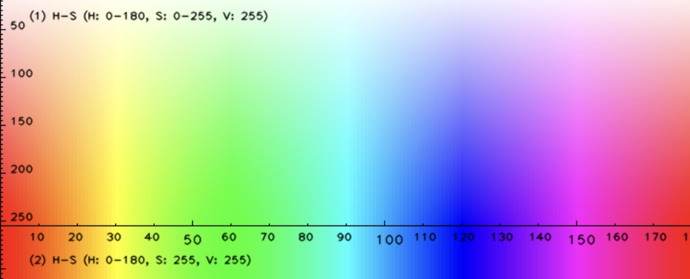
Fig 12.1 HSV Hue spectrum (0–180 in OpenCV). Yellow ≈ Hue 25–35. Note: OpenCV uses 0–180 for Hue instead of the standard 0–360 — divide any standard hue value by 2.
Channel
Range
Low Extreme
High Extreme
Hue (H)
0–180 (OpenCV)
Red tones (0)
Violet back to red (180)
Saturation (S)
0–255
White / desaturated gray (no color)
Pure vivid saturated color
Value (V)
0–255
Black / very dark (0)
Bright, fully lit (255)
What You Should See in the GUI
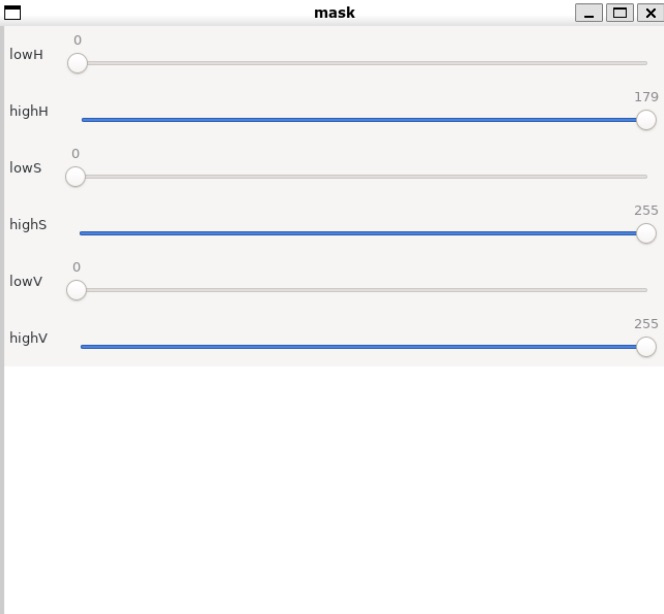
Fig 12.2 Default slider values — the entire image passes through the filter and appears white. No useful detection is possible. This is your starting point before tuning.
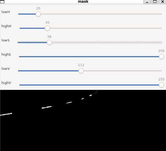
Fig 12.3 Target result: tuned for yellow road dots (lowH=25, highH=35, lowS≈56, lowV≈112). Only the yellow lane markers appear white; the rest is black. This is what you are working toward.
Step-by-Step Tuning Procedure
With the calibration launch running and the car on the track, adjust the sliders in the GUI in this order:
1
Set the Hue Range for Yellow
For the yellow lane markers used on the ECE/MAE 148 track, start with lowH = 25 and highH = 35. These values isolate the yellow-green to yellow-orange range. The mask preview should now show only roughly yellow regions as white.
2
Raise lowS to Filter Out Gray Road Surface
Increase lowS to approximately 50–80. This removes desaturated gray patches (the road itself) that might bleed into the yellow hue range under certain lighting. If the actual yellow dots start disappearing, lower lowS until they reappear.
3
Raise lowV to Eliminate Shadow Noise
Increase lowV to approximately 80–120. This removes dark shadow regions that might have a yellow hue component. Track shadows are a major source of false detections. Lower the value if shadowed portions of the actual yellow markers start disappearing.
4
Remove Remaining Speckle Noise
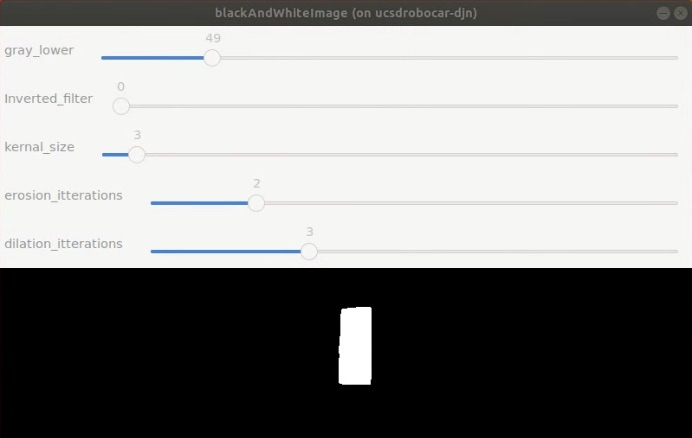
Use erosion_iterations to shrink all pixel blobs (removes small noise dots), then use dilation_iterations to expand the remaining valid blobs back (restores the real markers). Use gray_thresh to additionally eliminate near-gray pixels.
Fig 12.4 Noise reduction sliders. After tuning, the mask preview should show clean white rectangles (the yellow lane markers) against a solid black background with no stray speckles.
Color Quick Reference
Target Color
lowH
highH
Strategy
Yellow center dots ← primary target
25
35
Direct Hue filtering. This is what the car follows on the ECE/MAE 148 track.
White lane lines
0
180
Set inverted_filter=1, then tune S and V to exclude the gray road surface.
Orange cones
10
20
May vary with your specific cones and lighting.
Red stop line
0–10 or 165–179
Wrap-around
Red wraps at H=0/180 in OpenCV. May need two separate filter passes.
✓
Good HSV Calibration Result
The mask preview shows solid white blocks where the yellow markers are, clean black everywhere else, and no stray speckles on the road surface. When you move the car slightly, the white blocks shift position in the mask. Proceed to Section 13 to configure lane detection parameters — do not stop the launch.
13
Step 3 — Lane & Line Calibration on the Track
Configure contour filtering, error threshold, and camera alignment
Phase 1 · With GUI Running
🎯
Still on the track with the GUI running
Continue from Section 12 — do not stop the launch. These sliders configure how the filtered mask is converted into a steering error signal. The goal is a stable blue centroid dot that follows the yellow lane center as the car moves.
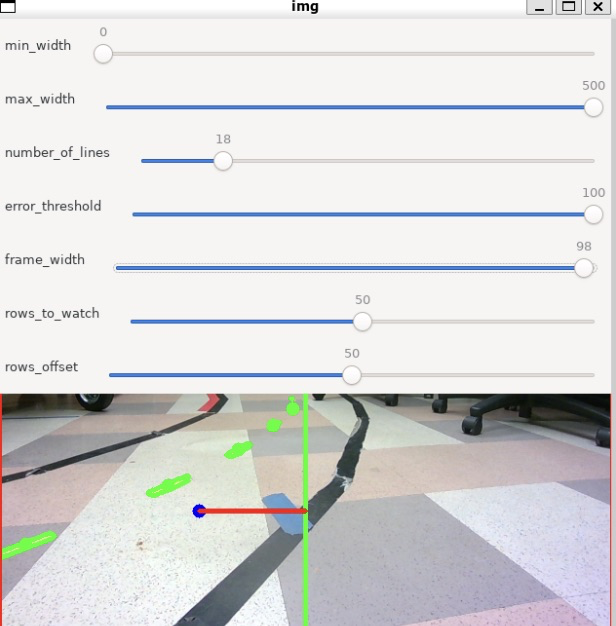
After the HSV filter produces a binary black-and-white image, the lane detection algorithm finds contours (connected white pixel groups), measures their widths, and computes a centroid. This centroid position is translated into a steering error signal for the PID controller.
Fig 13.1 Lane calibration view: green segments are valid detected markers, the blue dot is the computed centroid, and the green vertical bar is the camera centerline reference. Your goal is a stable, steady blue dot centered on the lane.
Contour Size Filtering
Parameter
Effect
Starting Value
min_width
Minimum pixel width for a contour to be accepted as a valid road marker. Eliminates thin, distant, or noisy detections.
15
max_width
Maximum pixel width. Filters out very wide blobs such as road surface color or shadows.
200
number_of_lines
How many valid line segments to include in the centroid calculation. More lines = more stable on straights, harder to tune on tight curves.
3–4
Error Threshold — The Dead Band
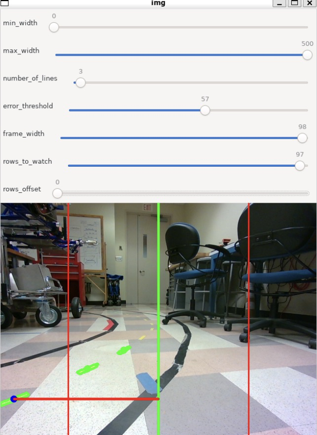
Fig 13.2 The two red vertical bars define the error threshold dead band. When the lane centroid falls between these bars, the error is treated as zero and no steering correction is applied.
The error threshold defines a "dead band" around the camera centerline. If the computed lane centroid falls within this zone, the robot treats the error as zero and makes no steering correction. This prevents constant micro-corrections on straight sections.
Scenario
Threshold Too Wide
Threshold Too Narrow
Straight sections
Small drifts uncorrected → car gradually wanders off center
Reacts to nearest markers → tighter, more aggressive turns
Camera Alignment & Cropping
Fig 13.3 Camera alignment view: the green bar marks the zero-error centerline reference (align this to the car's physical center), and the red bars show the error threshold bounds.
Parameter
Effect
camera_centerline
Sets the position of the green zero-error reference bar. Place a ruler along the car's physical centerline and adjust this slider until the green bar aligns with it.
frame_width
Crops the image horizontally. Reduces analysis columns to ignore walls and off-track objects at frame edges.
rows_to_watch
Crops the image vertically — controls how many rows from the bottom are analyzed. Smaller = focuses on road immediately ahead; larger = looks further ahead.
rows_offset
Shifts the vertical crop window up/down. Higher offset makes the car "look" further down the road, useful for anticipating curves at higher speeds.
✓
Lane Calibration Complete — Ready for Phase 2
When the blue centroid dot tracks the yellow lane markers steadily and the error threshold bars are positioned appropriately, you are done with Phase 1 calibration. Press Ctrl+C to stop the launch and proceed to Section 14 to switch to navigation mode and tune PID on the track.
14
Step 4 — Switch to Navigation Mode & Tune PID
Change the nodes, launch the car autonomously, and dial in PID gains on the track
Phase 2 · Car Moves
✗
Safety — Read Before the Car Moves
Never launch navigation mode with the robot on the track without at least one person positioned to physically stop it. Always have Ctrl+C ready in the launch terminal. Start at minimum throttle and verify behavior before increasing speed.
Phase 2, Part A — Edit node_config.yaml to Navigation Mode
Stop the calibration launch (Ctrl+C if it is still running), then change node_config.yaml to switch from calibration to autonomous driving:
🔁
Workflow: Edit node_config.yaml → build_ros2 → test → repeat
node_config.yaml — set these exact values for NAVIGATION MODE
all_components: 1
camera_nav_calibration: 0 # ❌ DISABLE — calibration GUI not needed during racingsensor_visualization: 0 # ❌ DISABLE — saves CPU cycles for the control loopcamera_nav: 1 # ✅ ENABLE — activates autonomous lane following
Inside Docker — build after changing node_config.yaml
build_ros2# Wait for "Build complete ✓"
Phase 2, Part B — Actuator Calibration (Steering & Throttle Limits)
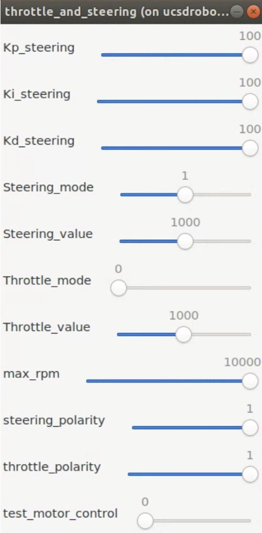
Before tuning PID, set physical limits for your steering servo and throttle. These are saved in ros_racer_calibration.yaml and are set using the actuator GUI sliders during a short calibration launch.
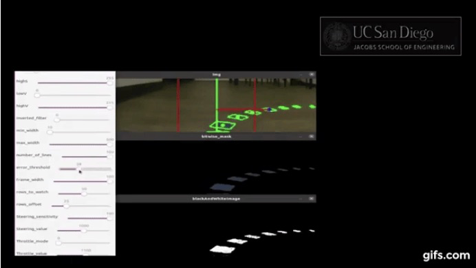
Fig 14.1 Actuator calibration GUI. Set steering physical limits first (modes 0, 1, 2 in order), then throttle limits.
Mode
Sets
Procedure
Steering_mode = 0
Maximum LEFT steering limit
Adjust Steering_value until wheels reach mechanical full-left stop. Switch to Mode 1 — value saves automatically when you switch.
Steering_mode = 1
STRAIGHT (zero error) value
Drive on flat surface. Adjust until car tracks perfectly straight with no steering input.
Steering_mode = 2
Maximum RIGHT steering limit
Adjust until wheels reach mechanical full-right stop. Switch back to Mode 0 to save.
Mode
Sets
Procedure
Throttle_mode = 0
zero_throttle (neutral / stopped)
Find the value at which the VESC makes no sound and the car does not move.
Throttle_mode = 1
max_throttle (full speed)
Increase in small increments only. Use a prop stand with wheels off the ground first. Typical values: 0.38–0.42.
Throttle_mode = 2
min_throttle (minimum moving speed)
Find the minimum value that actually moves the car forward on the track surface.
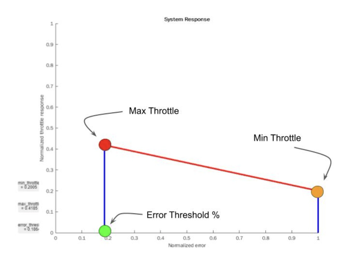
Fig 14.2 Throttle scheduling: the car runs at max_throttle when lane tracking error is low (straights) and decreases linearly to min_throttle as error increases (sharp curves).
Phase 2, Part C — PID Steering Gains (Tuned While Driving)
PID tuning is an iterative process done on the track with the car driving. Start with conservative values below, launch the car, observe the behavior, then edit the YAML and rebuild. Repeat until the car follows the lane smoothly.
lane_guidance_node:
ros__parameters:
Kp_steering: 0.4# Start here — increase if sluggish, decrease if oscillatingKi_steering: 0.01# Keep near zero unless car has a persistent one-sided driftKd_steering: 0.1# Increase to dampen oscillationzero_throttle: 0max_throttle: 0.382# Moderate speed — increase carefully after verifying straight trackingmin_throttle: 0.363# Minimum to overcome static friction on your track surfaceerror_threshold: 0.15# Dead band (0–1 normalized error scale)max_right_steering: 1max_left_steering: -1
vesc_twist_node:
ros__parameters:
steering_polarity: 1# Change to -1 if steering direction is reversedthrottle_polarity: 1# Change to -1 if the car drives backward instead of forwardmax_potential_rpm: 20000zero_throttle: 0max_throttle: 0.382min_throttle: 0.363straight_steering: 0max_right_steering: 1max_left_steering: -1
⚠
build_ros2 After Every YAML Edit — No Exceptions
After saving any change to ros_racer_calibration.yaml, you must run build_ros2. Simply saving the file is not enough — ROS2 won't see the new values until after a rebuild and re-launch.
Launch the Car Autonomously
Inside Docker — launch autonomous lane following
source_ros2build_ros2# Always build before launching to catch any unsaved YAML changesros2 launch ucsd_robocar_nav2_pkg all_nodes.launch.py
PID Symptom-Fix Table — On-Track Reference
What You See on Track
Most Likely Cause
Fix (edit YAML → build_ros2 → relaunch)
Rapid left-right oscillation on straights
Kp_steering too high or Kd_steering too low
Reduce Kp_steering by 0.05–0.1. Increase Kd_steering by 0.05.
Consistent drift to one side on straights
camera_centerline miscalibrated or Ki_steering too low
Recalibrate centerline (Section 13). Add small Ki_steering (e.g., 0.01).
Slow/sluggish correction in curves
Kp_steering too low or error_threshold too wide
Increase Kp_steering. Narrow error_threshold.
Flies off the track on tight curves
max_throttle too high, error_threshold too wide
Reduce max_throttle. Widen error_threshold so throttle scheduling slows car earlier.
Insufficient USB power to OAK-D or HSV not calibrated
Use powered USB hub (Section 8). Re-run HSV calibration (Section 12).
Live Debug Overlay
Second terminal (while car is running)
ros2 param set /lane_detection_node debug_cv 1# Turn ON visual overlay windowros2 param set /lane_detection_node debug_cv 0# Turn OFF (reduces CPU during racing)
15
ROS2 Nodes, Topics & Subscribers — Dev Guide
Write custom nodes, integrate sensors, and reuse existing packages
This section gives you the foundation to extend the Robocar framework for your team's custom project. Understanding the existing node graph lets you intercept live data, add new behaviors, and reuse pre-built functionality without rewriting code that already exists.
Node Architecture — Data Flow
Node
Publishes
Subscribes To
Hardware
/camera_node
/camera/color/image_raw
—
OAK-D Camera
/lane_detection_node
/error (Float32, –1 to 1)
/camera/color/image_raw
—
/lane_guidance_node
/cmd_vel (Twist)
/error
—
/vesc_twist_node
Hardware PWM signals
/cmd_vel
VESC ESC → Motor + Servo
/lidar_node
/scan (LaserScan)
—
RPLiDAR (if installed)
Custom Subscriber Node — Full Working Example
my_custom_node.py — place in your package directory
#!/usr/bin/env python3
import rclpy
from rclpy.node import Node
from std_msgs.msg import Float32
from geometry_msgs.msg import Twist

class LaneErrorMonitor(Node):
    def __init__(self):
        super().__init__('lane_error_monitor')
        self.sub = self.create_subscription(Float32, '/error', self.error_callback, 10)
        self.pub = self.create_publisher(Twist, '/cmd_vel', 10)
        self.get_logger().info('LaneErrorMonitor started!')

    def error_callback(self, msg: Float32):
        self.get_logger().info(f'Error: {msg.data:.4f}')
        if abs(msg.data) > 0.8:
            self.get_logger().warn('CRITICAL ERROR — sending stop command!')
            self.pub.publish(Twist())  # Zero velocity to stop the car

def main(args=None):
    rclpy.init(args=args)
    node = LaneErrorMonitor()
    try:
        rclpy.spin(node)
    except KeyboardInterrupt:
        pass
    finally:
        node.destroy_node()
        rclpy.shutdown()

if __name__ == '__main__':
    main()
build_ros2ros2 run ucsd_robocar_nav2_pkg lane_monitor
✓
Check What Already Exists First
Before writing any new code, run ros2 topic list and ros2 node list. The sensor data you need is almost certainly already being published. Subscribing to an existing topic takes about 10 lines of code. Writing a new hardware driver from scratch takes hundreds.
Package
What It Provides
How to Use It
ucsd_robocar_sensor2_pkg
Camera publisher, LiDAR publisher, IMU data
Enable in car_config.yaml. Subscribe to the published topics.
ucsd_robocar_lane_detection2_pkg
Full HSV pipeline → publishes to /error
Subscribe to /error (Float32, –1 to 1) to build your own controller.
ucsd_robocar_actuator2_pkg
VESC hardware driver — accepts /cmd_vel
Publish Twist messages to /cmd_vel. That is all that is required.
ucsd_robocar_nav2_pkg
Launch files and the YAML config system
Copy existing launch files as starting templates for custom node graphs.
16
Troubleshooting & Known Issues
Quick reference for the most common failure modes
Docker & System
Problem
Fix
docker: permission denied
Run sudo usermod -aG docker $USER then fully log out and back in
"Container name already in use"
Use docker start MY_CONTAINER_NAME then docker exec -it MY_CONTAINER_NAME bash
Container not found after Pi reboot
Run docker start MY_CONTAINER_NAME — container exists on disk, just stopped
"No space left on device"
Run docker system prune -f to remove dangling images and stopped containers
X11 & Display
Error
Fix
"cannot open display"
Reconnect with the -Y flag: ssh -Y pi@ucsdrobocar-148-XX.local
"No protocol specified"
Run on the Pi host (not inside Docker): xhost +local:
"Authorization required" inside Docker
Ensure --volume $HOME/.Xauthority:/root/.Xauthority:rw is in your docker run command
GUI works on Pi host but not inside container
Switch from ssh -X to ssh -Y and recreate or restart the container
Camera & Hardware
Problem
Fix
OAK-D disconnects randomly
Use a powered USB hub — see Section 8
All-black camera feed
Insufficient USB power — a powered USB hub is required
VESC not responding
Check the USB cable. Run dmesg | grep usb and look for enumeration errors
Wheels spin backward
Set throttle_polarity: -1 in ros_racer_calibration.yaml, then build_ros2
Steering direction inverted
Set steering_polarity: -1 in ros_racer_calibration.yaml, then build_ros2
Receiving another team's robot data
Set ROS_DOMAIN_ID — see Section 9. Always the cause of this problem.
Build & ROS2
Problem
Fix
"Package not found" after a successful build
Run source_ros2. The build succeeded, but ROS2 has not been told about the new packages yet.
YAML changes have no effect
You must run build_ros2 — source_ros2 alone is not enough. Most common student mistake.
"Launch file not found"
Verify setup.py includes the launch/ directory, then re-run build_ros2.
Calibration GUI closes immediately
X11 is not working inside Docker. Verify: echo $DISPLAY inside container — must not be empty.
PID & Lane Following
Symptom
Fix (always followed by build_ros2 + relaunch)
Rapid left-right oscillation
Reduce Kp_steering. Increase Kd_steering.
Consistent drift in one direction
Recalibrate camera_centerline. Add small Ki_steering (e.g., 0.01).
Too fast on curves, flies off track
Reduce max_throttle. Widen error_threshold.
No response to curves, goes straight
Narrow error_threshold. Increase Kp_steering.
No lines detected in debug view
Recalibrate HSV on the track — lighting changes throughout the day.
UCSD Jacobs School of Engineering — ECE/MAE 148 Intro to Autonomous Vehicles