Complete reference for ECE/MAE 148 — covering VESC Tool installation, firmware updates for VESC 6.x and 4.x hardware, FOC motor detection, hall sensor calibration, battery configuration, and servo steering setup for autonomous RC cars.
⚡VESC 6.x / EDU
🔧VESC Tool
🚗BLDC Motor
🔋LiPO Battery
01
Overview & Safety
Read this before touching any hardware
CRITICAL
The VESC (Vedder Electronic Speed Controller) is the motor driver used in all ECE/MAE 148 robots. It controls the BLDC (Brushless DC) drive motor and the servo motor used for steering. Before beginning setup, you must understand the hardware variants and safety requirements — choosing the wrong firmware version can permanently damage your VESC.
🛑
STAND REQUIREMENT — WHEELS MUST BE CLEAR
Place the robot on the class-provided stand before connecting anything. The drive wheels will spin during motor detection — they must be completely clear of any surfaces, cables, your laptop, and your hands. This is not optional. Failure to use the stand can result in injury or damaged hardware. This warning appears multiple times in this guide intentionally.
⚠
DO NOT Disconnect During Firmware Update
Never remove power or the USB cable from the VESC while firmware is uploading. Doing so will almost certainly brick the VESC, requiring a programmer to recover it. Wait for the "Upload done" confirmation before touching any cables.
VESC Hardware Versions in This Class
There are multiple VESC hardware variants used across different semesters. Identifying yours correctly before flashing firmware is critical — flashing the wrong firmware will break your VESC.
Hardware
Identifier in VESC Tool
Firmware Track
Notes
VESC 6 EDU
Hw: EDU
v6.00 (VESC_default.bin)
Primary class hardware as of Fall 2022
Original VESC 6.x
Hw: 60
v6.00 (VESC_default.bin)
Can upgrade to the latest firmware
FLIPSKY FSESC 6.6
Hw: 60 or similar
v6.00
VESC 6.x compatible — follow VESC 6 instructions
FLIPSKY FSESC 6.7
Hw: 60 or similar
v6.00
VESC 6.x compatible — follow VESC 6 instructions
VESC 4.12 / FLIPSKY Mini FSESC4.2
Hw: 412
v4.2 (VESC_servoout.bin)
Legacy. Use VESC Tool v2.03 only. Do NOT upgrade firmware.
ℹ
Which Hardware Do You Have?
Look at the physical board label, or connect with VESC Tool and read the hardware version shown in the bottom status bar and the Firmware section. If you see Hw: EDU or Hw: 60, follow the VESC 6.x instructions (Sections 4–5). If you see Hw: 412, follow the legacy VESC 4.x instructions (Section 6).
02
Required Hardware
Everything you need before starting
Gather all hardware listed below before starting. Using the wrong battery or cable during a firmware update can damage the VESC.
Item
Specification
Why It's Needed
RC Car Battery (LiPO/LiIon)
3S or 4S depending on your robot — ECE/MAE 148 uses 3S (3-cell, 3 Ah) by default
The VESC must be powered by the same battery you plan to use during operation. Using a different power source produces incorrect motor calibration values.
LiPO Battery Alarm
Must match your battery's cell count
Monitors each cell's voltage and beeps when any cell drops too low. This protects the battery from over-discharge during the motor detection spin cycle, which can run for several seconds.
Micro-USB Cable (long)
At least 1 m recommended
Connects the VESC to your host PC. Must be long enough to keep your PC away from the spinning wheels. Ask a TA if you need a longer cable.
Host PC
Windows, macOS, or Linux with a USB port
Runs VESC Tool for firmware update and configuration. Use your laptop — not the Raspberry Pi.
Class-provided robot stand
Lifts all four wheels off the ground
Wheels spin freely during motor detection. The stand prevents the robot from driving off the table.
BLDC drive motor
Sensored (includes a hall sensor connector)
The class uses sensored BLDC motors for precise low-speed control. The hall sensor cable plugs separately into the VESC.
Steering servo motor
Standard RC servo (PWM)
Controls left/right steering. It is driven by a PWM signal from the VESC's servo output pin.
03
Install VESC Tool
Use the class-provided version to ensure identical firmware across all robots
The entire class uses the same version of VESC Tool to keep firmware versions consistent between robots. Using a different version may produce incompatible firmware builds or missing firmware files (such as VESC_servoout.bin for legacy 4.x hardware).
⚠
Use the Class-Provided VESC Tool
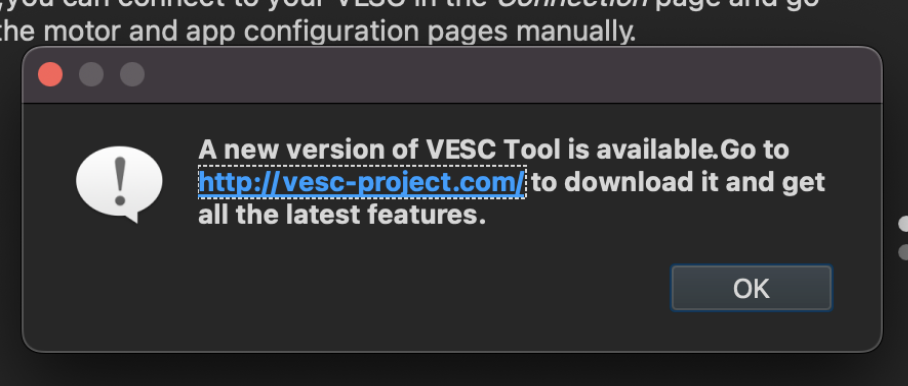
When VESC Tool opens, it may prompt you to download a newer version. Dismiss this warning and do not upgrade unless you are using the class-provided version. The instructor provides a specific version that matches the firmware used on all class robots.
1
Download the Class-Provided VESC Tool
Get the VESC Tool version specified by your instructor from the class Google Drive folder linked below. This folder contains the exact version used in class for both VESC 6.x and VESC 4.x hardware.
📥
Class VESC Tool — Google Drive Download
Download the class-provided VESC Tool from the shared Google Drive folder:
https://drive.google.com/drive/folders/1m_gqcIWwaCzV3y3raU1FFiEpCyf3rYPi?usp=sharing
# Download the binary for your OS from this shared folder
VESC 4.x legacy — VESC Tool v2.03 (fallback)
https://github.com/rpasichnyk/vesc_tool/releases/tag/v2.03
# Download the binary for your OS from this release page
2
Install and Launch VESC Tool
On Windows, run the installer. On macOS, drag the app to Applications. On Linux, extract the archive and run the AppImage. Launch the tool and dismiss any "newer version available" prompts.
🖼
Fig 01 — Version Warning Popup
A dialog saying "A new version of VESC Tool is available" with an OK button. Click OK to dismiss — do not follow the upgrade link.
Fig 01
Version upgrade warning — click OK to dismiss; do not follow the upgrade link
✓
Dismiss Version Warnings
If you see a popup saying "A new version of VESC Tool is available", click OK to dismiss it. Do NOT click the link to download a newer version unless instructed by the TA.
04
Connect the VESC to Your Host PC
Power and USB setup before opening VESC Tool
🛑
Robot Must Be on the Stand
Place the robot on the class-provided stand. All wheels must be completely clear and able to spin freely. Keep your laptop and hands away from the wheel path at all times.
1
Disconnect the VESC from the Raspberry Pi
If the VESC is currently plugged into the SBC (Single Board Computer — the Raspberry Pi), unplug the USB cable from it. For this procedure, the VESC must connect directly to your host laptop, not the Raspberry Pi.
2
Connect the LiPO Battery Alarm
Plug the LiPO battery alarm into the battery's balance plug (the small multi-pin connector on the side of the battery) before connecting the battery to the VESC. This monitors each cell's voltage and protects the battery from being over-discharged during the motor detection spin cycle.
3
Connect the Battery to the VESC
Plug the RC car battery into the VESC's main power input. Use the same battery you plan to use during robot operation — the motor calibration values depend on supply voltage, so using a different power source will produce incorrect results.
4
Connect the VESC to Your Host PC via Micro-USB
Plug the micro-USB cable into the VESC and the other end into your laptop. Use a cable long enough that your laptop is kept well clear of the spinning wheels. Make sure the cable is a data cable, not a charge-only cable — charge-only cables will not be recognized by VESC Tool.
5
Open VESC Tool and Connect
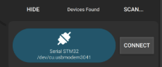
Launch VESC Tool on your laptop. Click the connect icon (plug symbol) in the top-left toolbar, or open the Connection panel, click SCAN, then click CONNECT on the detected device.
🖼
Fig 02a — Connect Icon
The plug-shaped connect icon in the VESC Tool top-left toolbar. Click this to connect.
Fig 02a Connect icon in the toolbar
🖼
Fig 02b — Connection Panel
The Connection panel showing a detected VESC device with SCAN and CONNECT buttons.
Fig 02b Connection panel — click SCAN, then CONNECT
VESC Tool connection flow
1. Click the plug/connect icon OR2. Connection panel → SCAN → select your device → CONNECT# Expected output in the status bar:Connected to VESC Fw: v6.00, Hw: EDU # (example — your version may differ)
🖼
Fig 03 — Test Firmware Warning
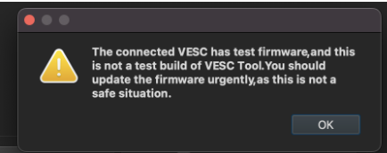
A warning dialog: "The connected VESC has test firmware, and this is not a test build of VESC Tool." Click OK to dismiss.
Fig 03 Test firmware warning — click OK; VESC 6.x users proceed to update, VESC 4.x users do NOT update
ℹ
Firmware Version Warning at Connection
VESC Tool may display "The connected VESC has test firmware and this is not a test build of VESC Tool." This is expected and safe to dismiss. For VESC 6.x: dismiss and proceed to Section 5 to update. For VESC 4.x: dismiss and proceed to Section 6 — do NOT update from the standard firmware list.
05
Firmware Update — VESC 6.x
Update to firmware v6.00 for all VESC 6.x hardware (EDU, original 6.x, FLIPSKY 6.6/6.7)
VESC 6.x ONLY
After connecting, identify your hardware version in the Firmware panel. VESC 6.x devices (including VESC EDU) should be updated to firmware v6.00 using VESC_default.bin. This ensures your VESC runs the same software as all other robots in class.
How to Identify Your Hardware Version
When connected in VESC Tool, look at the bottom-left status area and the Firmware panel. You should see one of the following hardware identifiers:
Hardware Shows
Firmware File
Action
Hw: EDU
VESC_default.bin (EDU row)
Update to v6.00
Hw: 60
VESC_default.bin (60 row)
Update to v6.00
Hw: 412
VESC_servoout.bin (v4.2)
Skip to Section 6 — do NOT update here
1
Open the Firmware Panel
In the VESC Tool left navigation sidebar, click Firmware. You will see a list of hardware versions, each paired with a firmware file. Find your hardware version in the list (EDU or 60).
🖼
Fig 04 — Firmware in Sidebar
VESC Tool left sidebar with the Firmware menu item highlighted in blue.
Fig 04 Click Firmware in the left sidebar to open the firmware panel
2
Select Your Hardware Row and Click Update
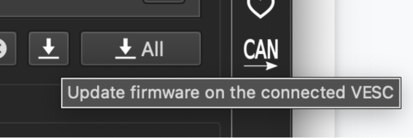
Select the row matching your hardware version (e.g., EDU → VESC_default.bin). Click the single download arrow button labeled "Update firmware on the connected VESC". Do not click "↓ All" — that flashes all connected VESCs and is not needed here.
🖼
Fig 05 — Hardware Row Selected
Firmware list with hardware version "60" highlighted and VESC_default.bin shown in the firmware column. Select your matching row.
Fig 05 Select your hardware row (EDU or 60) — VESC_default.bin will be flashed
🖼
Fig 06 — Firmware Toolbar Buttons
Toolbar with a single download arrow (↓) and a "↓ All" button. Use the single arrow only.
Fig 06 Use the single ↓ arrow — not ↓ All
🖼
Fig 07 — Download/Flash Button
The large download arrow button used to start the firmware upload.
Fig 07 Click the download button to begin the firmware upload
3
Confirm the Firmware Overwrite Warning
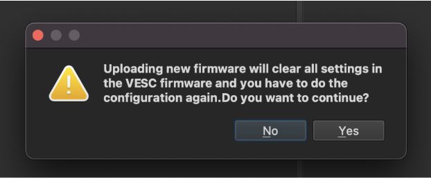
A dialog appears: "Uploading new firmware will clear all settings in the VESC firmware and you have to do the configuration again. Do you want to continue?" Click YES. All settings will be cleared — this is expected. You will reconfigure everything during the motor detection steps that follow.
🖼
Fig 08 — Overwrite Confirmation
Dialog asking to confirm firmware overwrite. Click YES to proceed.
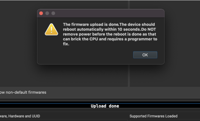
After clicking YES, do not disconnect power or the USB cable until you see "Upload done" in the status bar. The VESC will automatically reboot within 10 seconds after the upload completes. Do not touch anything until the reboot finishes.
4
Verify the Successful Upload
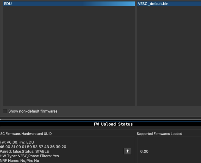
After the VESC reboots, reconnect in VESC Tool. The status bar should show the new firmware version. For VESC EDU, you will see Fw: v6.00, Hw: EDU. For a standard VESC 6.x, you will see Fw: v6.00, Hw: 60.
🖼
Fig 09a — Upload Done Dialog
Dialog: "The firmware upload is done. The device should reboot automatically within 10 seconds. Do NOT remove power before the reboot is done." Click OK.
Fig 09a Upload done dialog — do not remove power until reboot completes
🖼
Fig 09b — Upload Done Status Bar
VESC Tool bottom status bar showing "Upload done" text.
Fig 09b "Upload done" in the status bar — wait for the automatic reboot
🖼
Fig 10 — Successful Firmware Update
Firmware panel after a successful update showing status: Fw: v6.00, Hw: EDU, Status: STABLE.
Fig 10
Successful update — status bar shows Fw: v6.00, Hw: EDU (or Hw: 60 for non-EDU boards)
Expected status after a successful VESC 6.x firmware update
Fw: v6.00, Hw: EDU
Paired: false, Status: STABLE
HW Type: VESC, Phase Filters: Yes
NRF Name: No, Pin: No

# Status bar shows: "Upload done" then VESC reboots automatically
✓
Firmware Update Complete
Once you see "Upload done" and the VESC has rebooted (about 10 seconds), it is safe to proceed. The next section covers connecting the motor and servo cables before running motor detection.
06
Firmware Update — VESC 4.x Legacy
Special servo-out firmware for VESC 4.12 / FLIPSKY Mini FSESC4.2
LEGACY ONLY
ℹ
VESC 6.x Users — Skip This Section
If you completed Section 5 (VESC 6.x firmware update), skip directly to Section 7 (Cable Connections). This section is only for robots still using VESC 4.x hardware.
VESC 4.x hardware requires a special firmware called VESC_servoout.bin. This firmware repurposes one of the VESC's PWM input pins to work as a PWM output, allowing the VESC to drive the steering servo motor. The latest versions of VESC Tool do not include this firmware file — you must use VESC Tool v2.03, which ships with firmware v4.2 containing VESC_servoout.bin.
⚠
DO NOT Upgrade VESC 4.x Firmware Beyond v4.2
For VESC 4.x hardware (e.g., V4.2, Hw: 412), do NOT flash any newer firmware. Later firmware versions for 4.x hardware do not include VESC_servoout.bin, which is required for servo steering. Use VESC Tool v2.03 and stay on firmware v4.2.
1
Download VESC Tool v2.03 (Required for 4.x)
Download the pre-built release from the repository link below. Do not use any other version — only v2.03 includes the VESC_servoout.bin firmware file for 4.x hardware.
In VESC Tool v2.03, navigate to the Firmware panel. Find hardware version 4.12 in the list and select VESC_servoout.bin — do not select the default VESC_default.bin. Click the update button to flash the firmware. The servoout build enables the PWM output pin needed to drive the steering servo.
🛑
DO NOT Disconnect During Upload
The same rules apply as for VESC 6.x: never disconnect power or the USB cable during a firmware upload. Wait for "Upload done" and the automatic reboot before proceeding.
3
Alternative Firmware Source (if needed)
If VESC Tool v2.03 does not include the servoout firmware for your specific 4.x hardware revision, the following repository contains archived v4.2 firmware files:
After flashing VESC_servoout.bin on your VESC 4.x, continue with Section 7 (Cable Connections) and follow the same motor detection steps as VESC 6.x — the FOC wizard procedure is identical for both hardware versions.
07
Cable Connections
Connect the motor, sensors, and servo before running motor detection
🛑
Disconnect Power Before Connecting Cables
Remove the battery from the VESC before connecting or disconnecting any motor or servo cables. Never plug or unplug motor phase wires while the VESC is powered — doing so creates large voltage spikes that can destroy the VESC's internal FETs (power transistors).
1
Disconnect the Battery and USB
Before connecting any motor cables, remove the battery connector from the VESC. Also unplug the USB cable from the host PC. The VESC must be completely unpowered before you touch any motor wires.
2
Connect the BLDC Drive Motor (Phase Wires)
Connect the three motor phase wires from the BLDC motor to the three motor output terminals on the VESC. These are usually bullet connectors or wires labeled A, B, and C. The order does not need to be perfect right now — you can reverse the motor direction in software if the motor spins the wrong way after detection.
3
Connect the Motor Hall Sensor Cable
Connect the motor's hall sensor cable to the VESC's sensor input port. This is typically a 6-pin JST connector (a small, keyed locking wire connector common in RC electronics). It carries three hall sensor signals plus 5 V power and ground. These sensors tell the VESC exactly where the motor rotor is at any given moment, enabling smooth and precise low-speed control.
4
Connect the Steering Servo
Connect the servo motor's 3-pin connector (signal / power / ground) to the VESC's PWM servo output port. The signal wire is typically white or yellow. Consult your VESC variant's pinout diagram if you are unsure of the pin order.
5
Reconnect the LiPO Battery Alarm and Battery
Plug the LiPO alarm's balance plug connector back into the battery, then reconnect the main battery to the VESC.
6
Reconnect USB and Open VESC Tool
Plug the USB cable back into the host PC. Launch VESC Tool and reconnect to the VESC using the connect button or the Connection panel.
🖼
Fig 11 — Reconnect After Cabling
The VESC Tool connect icon — click this to reconnect once all cables are in place.
Fig 11 Reconnect VESC Tool after completing all cable connections
Cable
From
To (VESC Port)
Purpose
3× Motor Phase Wires
BLDC Motor (A, B, C)
Motor output terminals
Delivers power to the motor's three coil windings
6-pin Hall Sensor JST
Motor sensor port
VESC sensor input
Provides rotor position data for FOC control
3-pin PWM Servo
Steering servo motor
VESC servo/PWM output
Receives the steering PWM signal from the VESC
Battery Main Connector
LiPO/LiIon battery
VESC power input
Main power supply
Balance Plug
LiPO battery side connector
LiPO alarm monitor
Monitors individual cell voltages to prevent over-discharge
08
FOC Motor Detection Wizard
Use the Setup Motors FOC wizard to automatically detect motor parameters
🛑
Last Chance — Is the Robot on the Stand?
The motor detection process will spin the wheels. Confirm the robot is elevated on the class stand and all four wheels are completely clear of any contact before proceeding.
The FOC (Field-Oriented Control) wizard automatically measures your motor's resistance, inductance, and flux linkage, then configures the VESC with optimal control parameters. FOC provides smoother, more efficient motor control than older methods. Running this wizard replaces manual parameter entry and produces accurate, motor-specific calibration values.
1
Navigate to Welcome & Wizards → Setup Motors FOC
In the VESC Tool left sidebar, click Welcome & Wizards. Then click the Setup Motors FOC button. A dialog will appear asking about loading default parameters.
🖼
Fig 12a — Wizards Menu
VESC Tool sidebar with "Welcome & Wizards" highlighted in blue.
Fig 12a Click Welcome & Wizards in the sidebar
🖼
Fig 12b — Setup Motors FOC Button
The large "Setup Motors FOC" button in the wizard panel.
Fig 12b Click Setup Motors FOC to launch the wizard
2
Load Default Parameters — Click YES
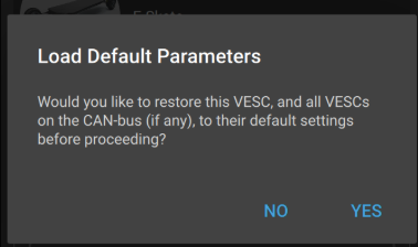
A dialog appears: "Would you like to restore this VESC, and all VESCs on the CAN-bus (if any), to their default settings before proceeding?" Click YES. This ensures a clean starting state and prevents any old, misconfigured settings from interfering with the detection.
🖼
Fig 13 — Load Default Parameters
Dialog asking to restore default settings. Click YES.
Fig 13 Load Default Parameters — click YES
3
Select Motor Usage: Generic
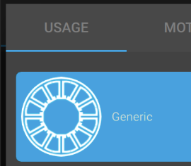
On the USAGE tab, select Generic. Do not select a specific application profile — Generic applies appropriate FOC parameters for a wide range of BLDC motors without making assumptions about the load type.
🖼
Fig 14 — USAGE Tab
FOC wizard USAGE tab with the "Generic" option highlighted in blue.
Fig 14 Select Generic on the USAGE tab
4
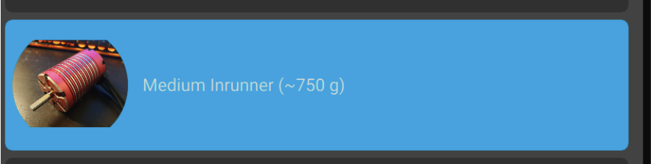
Select Motor Type: Medium Inrunner (~750 g)
On the MOTOR tab, select Medium Inrunner (~750 g). An inrunner motor has the spinning rotor on the inside (unlike an outrunner where the outer shell spins). This preset sets appropriate current limits and FOC tuning parameters for the class RC car motors (such as the XeRun 3660 G2 and similar sensored inrunner motors in the 700–800 g range).
🖼
Fig 15 — Motor Type Selection
FOC wizard Motor tab with "Medium Inrunner (~750 g)" highlighted in blue.
Fig 15 Select Medium Inrunner (~750 g) on the MOTOR tab
ℹ
Why Medium Inrunner?
Using the wrong motor size preset can cause jerky performance or trigger over-current faults. The Medium Inrunner preset matches the physical and electrical characteristics of the motors in this class. If you are unsure whether your motor qualifies, ask a TA to confirm before proceeding.
09
Battery Configuration
Set the correct battery type, cell count, and capacity
Correct battery configuration is critical for safety. The VESC uses these settings to calculate low-voltage cutoff thresholds — the point at which it shuts down to protect the battery. Using the wrong cell count can result in either premature shutdowns (annoying but safe) or, more dangerously, allowing the LiPO/LiIon battery to over-discharge, which causes permanent cell damage and creates a fire risk.
⚠
Check Your Physical Battery Label
Look at the label on your battery before entering values. The cell count (marked as "S") and capacity (in Ah) are printed on the battery itself. Do not assume — getting this wrong can damage the battery. ECE/MAE 148 generally uses 3S 3 Ah batteries. DSC 178 and racing robots use 4S 4 Ah.
Course / Robot
Battery Cells (Series)
Battery Capacity
Battery Type
ECE/MAE 148
3 (3S)
3.000 Ah
BATTERY_TYPE_LIION_3_0__4_2
DSC 178 / Racing
4 (4S)
4.000 Ah
BATTERY_TYPE_LIION_3_0__4_2
1
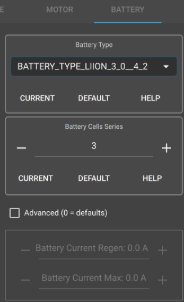
Set Battery Type, Cell Count, and Capacity
In the Battery tab of the FOC wizard, set Battery Type to BATTERY_TYPE_LIION_3_0__4_2. Set Battery Cells Series and Battery Capacity to match your physical battery (see the table above).
🖼
Fig 16 — Battery Tab
FOC wizard Battery tab. Set Battery Type to BATTERY_TYPE_LIION_3_0__4_2 and enter your cell count and capacity from the battery label.
Fig 16
Battery tab — enter your cell count and capacity from the physical battery label
Battery settings in the FOC wizard
Battery Type: BATTERY_TYPE_LIION_3_0__4_2
# ECE/MAE 148:
Battery Cells Series: 3# 3-cell LiIon/LiPO battery
Battery Capacity: 3.000 Ah# As printed on the battery label# DSC 178 / Racing robots:
Battery Cells Series: 4# 4-cell LiIon/LiPO battery
Battery Capacity: 4.000 Ah# As printed on the battery label
2
Click Next to Continue
After setting the battery parameters, click Next to advance to the motor parameter configuration page.
10
Motor Parameters
Set pole count, gear ratio, and wheel diameter
The VESC needs accurate motor parameters to calculate correct RPM readings and speed control. The most important value is the number of magnetic poles on your motor — this directly affects all speed calculations.
Finding Your Motor's Pole Count
You must look up the pole count for your specific motor model. The pole count refers to the number of magnetic poles on the rotor (the spinning part inside the motor). It is not the same as the number of stator slots (the stationary coil slots on the outside). For the class example motor:
Example: XeRun 3660 G2 Sensored Motor
# Motor part number: XeRun 3660 G2# Manufacturer link:
https://www.hobbywingdirect.com/products/xerun-3660-g2-sensored-motor
# Spec: "innovative 14-pole-28-magnet staggered pole rotor"# Pole count to enter in the VESC wizard = 4# (Always verify against YOUR motor's datasheet — do not guess)
ℹ
How to Find Your Motor's Pole Count
Search the motor part number on the manufacturer's website or in its datasheet. Look for phrases like "X-pole rotor" or "X magnets". The number you enter in VESC Tool is the pole count only. Most small RC inrunner motors are 4-pole. If you cannot find the specification, ask a TA.
1
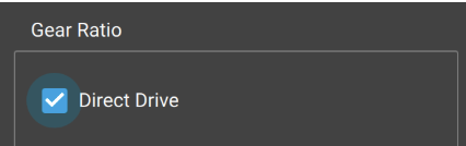
Set Gear Ratio: Direct Drive
In the wizard, select Direct Drive for gear ratio. The class RC cars use a direct-drive configuration where the motor connects to the drivetrain without an additional software-level gear ratio adjustment.
🖼
Fig 17 — Gear Ratio
FOC wizard Gear Ratio section with "Direct Drive" selected (blue checkmark).
Fig 17 Select Direct Drive for the gear ratio
2
Set Number of Motor Poles
Enter the pole count for your motor. For the XeRun 3660 G2 and most class motors, this is 4. Always verify against your motor's datasheet before entering a value.
Motor pole count entry
Motor Poles: 4# Verify against YOUR motor's datasheet
3
Set Wheel Diameter: 100.00 mm
Set the wheel diameter to 100.00 mm. This is the standard wheel size used on the class RC car platform. Accurate wheel diameter ensures that speed readings in m/s are correct when using the Robocar software framework later.
Wheel diameter setting
Wheel Diameter: 100.00 mm# Standard class RC car wheel
11
Run Detection & Motor Direction
Execute the FOC detection spin cycle and set the correct forward direction
🛑
Final Safety Check — Wheels Must Be Completely Clear
This step will physically spin the wheels. This is your last chance to verify the robot is elevated on the stand with all wheels free of any contact. Keep hands, cables, and your laptop away from the wheel path.
1
Click "Run Detection"
In the wizard, click Run Detection. The VESC will automatically measure resistance (R), inductance (L), and flux linkage (λ) by running controlled current pulses through the motor. The wheels will spin briefly forward, then backward during this process. Detection takes approximately 10–30 seconds.
ℹ
What Happens During Detection
The VESC sends precise current pulses into the motor and measures how it responds to calculate the motor's electrical properties (R, L, λ). These values are unique to your specific motor and wiring. The detected values shown in your wizard will differ from any example screenshots — that is completely normal and expected.
2
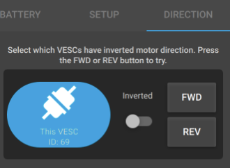
Set Motor Direction (FWD or REV)
After detection, the wizard shows a Direction screen with FWD and REV buttons. Press FWD — if the drive wheels spin forward (in the direction the car would drive forward), you are done. If the wheels spin backward when you press FWD, enable the Inverted toggle or press REV to reverse the direction. Confirm that pressing FWD makes the wheels spin forward before continuing.
🖼
Fig 18 — Direction Tab
FOC wizard DIRECTION tab showing FWD/REV buttons and an Inverted toggle. Press FWD and confirm the wheels spin forward.
Fig 18 Direction tab — press FWD and verify the wheels spin forward; toggle Inverted if they spin backwards
Direction determination logic
# Press FWD in the wizard direction tab# If wheels spin FORWARD:# → Leave direction as-is and continue# If wheels spin BACKWARD:# → Enable the "Inverted" toggle or press REV# → Re-test with FWD to confirm correction
3
Write Motor Configuration
Click the Write Motor Configuration button (the ↓M icon in the toolbar). This saves all detected motor parameters to the VESC's non-volatile memory (NVRAM — storage that retains data even when powered off). Without this step, all settings will be lost on the next power cycle.
🖼
Fig 19 — Write Motor Config (↓M)
The Write Motor Configuration toolbar button (↓M icon). Always click this after detection or after changing any motor settings.
Fig 19 Write Motor Configuration (↓M) — click after detection and after any motor setting change
Write motor configuration
# Click the ↓M button in the VESC Tool toolbar# OR: Motor Settings → Write Motor Configuration# Confirmation: "Motor configuration written"
4
Write App Configuration
Click the Write App Configuration button (the ↓A icon in the toolbar). This saves the application-layer settings — such as UART communication and servo output mode — to the VESC's non-volatile memory. Always write both motor and app configurations after making changes.
🖼
Fig 20 — Write App Config (↓A)
The Write App Configuration toolbar button (↓A icon). Click this to save app-layer settings.
# Click the ↓A button in the VESC Tool toolbar# OR: App Settings → Write App Configuration# Confirmation: "App configuration written"
✓
Front Wheels Not Turning?
If the front wheels do not move or steer at this stage, that is completely normal. Nothing is broken. The servo output needs to be enabled separately — this is covered in Section 13. Continue to Section 12 (Hall Sensor Detection) now.
12
Hall Sensor Detection
Detect and map the hall sensor table for sensored FOC operation
The FOC motor detection wizard in the previous section measures motor parameters (R, L, λ) but does not configure the hall sensors — that is a separate step. Hall sensors are small magnetic sensors mounted inside the motor that tell the VESC exactly where the rotor is positioned at any given moment. This is especially important at low speeds where sensorless estimation is unreliable.
Why Hall Sensor Detection Matters
Without correct hall sensor calibration, the motor operates in sensorless mode below the Sensorless ERPM threshold (ERPM = Electrical RPM, which equals the motor's pole count multiplied by the mechanical RPM). Sensorless operation at low speeds produces stuttering and jerky starts. With hall sensors properly mapped, the VESC transitions smoothly from sensored (low-speed) to sensorless (high-speed) operation as the motor spins up.
1
Navigate to Motor Settings → FOC → Hall Sensors Tab
In the VESC Tool left sidebar, click Motor Settings → FOC. In the tab bar at the top of the FOC panel, click the Hall Sensors tab. You will see the Sensor Mode dropdown and the Hall Table entries.
🖼
Fig 21 — Motor Settings FOC Panel
Motor Settings → FOC panel with tabs for General, Hall Sensors, and other options. Select the Hall Sensors tab.
Fig 21 Motor Settings → FOC panel — select the Hall Sensors tab at the top
2
Verify Sensor Mode is Set to "Hall Sensors"
The Sensor Mode dropdown should read Hall Sensors. If it shows Sensorless or Encoder, change it to Hall Sensors. This setting tells the VESC to use the connected hall sensor cable for rotor position feedback at low speeds.
🖼
Fig 22a — Sensor Mode: Hall Sensors
Large display showing "Sensor Mode" on the left and "Hall Sensors" on the right.
Fig 22a Sensor Mode set to Hall Sensors
🖼
Fig 22b — Hall Sensors Button
The Hall Sensors selection button/badge.
Fig 22b Hall Sensors selection button
Sensor Mode setting
Sensor Mode: Hall Sensors# Must be set to this value# NOT: Sensorless# NOT: Encoder
3
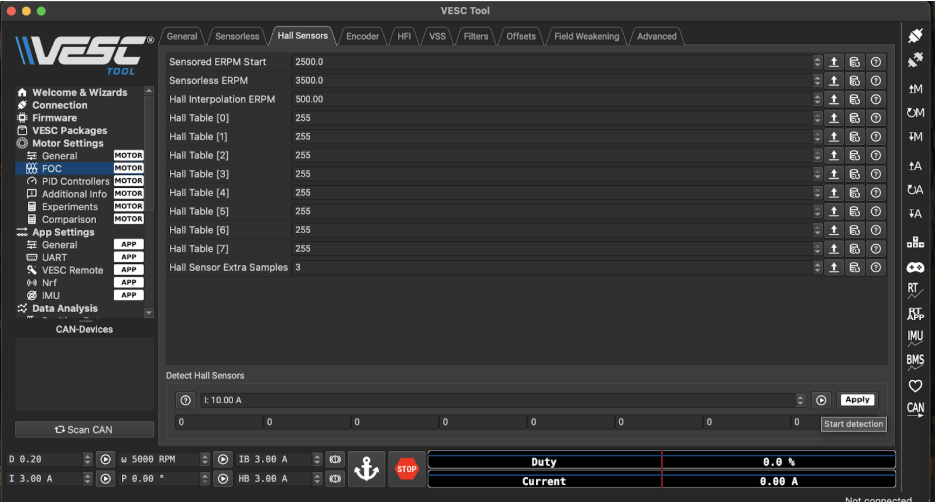
Run Hall Sensor Detection
At the bottom of the Hall Sensors tab, find the Detect Hall Sensors section. Leave the detection current at the default (10.00 A is appropriate for class motors). Click Start Detection. The motor will spin slowly while the VESC reads and maps the hall sensor pattern for every rotor position.
🖼
Fig 23 — Hall Table Before Detection
Hall Sensors tab before running detection — all Hall Table values show 255 (unconfigured). Click Start Detection to populate the table.
Fig 23 Hall Table showing all 255 (unconfigured) before detection — click Start Detection
⚠
Wheels Will Spin During Detection
The motor rotates during hall sensor detection. The robot must be on the stand with all wheels clear before clicking Start Detection.
4
Verify Hall Table Values and Click Apply
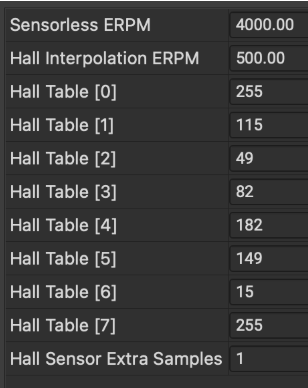
After detection, the Hall Table entries (Hall Table [0] through [7]) will be populated with numbers. These values are unique to your motor and its wiring — they will differ from any examples shown here. Click Apply to accept the detected values. A value of 255 in a table slot means that state is unused; this is normal for slots [0] and [7].
🖼
Fig 24 — Hall Table After Detection
Hall sensor table after detection — Hall Table [1]–[6] are populated with unique values. Your values will differ from this example.
Fig 24
Hall table after detection — your values will differ; this is expected and correct
Example hall sensor detection output (your values will differ)
# This is an EXAMPLE — do not manually enter these values# Your detected values will be different, and that is correct
Sensorless ERPM: 4000.00
Hall Interpolation ERPM: 500.00
Hall Table [0]: 255
Hall Table [1]: 115 # ← unique to your motor and wiring
Hall Table [2]: 49
Hall Table [3]: 82
Hall Table [4]: 182
Hall Table [5]: 149
Hall Table [6]: 15
Hall Table [7]: 255
Hall Sensor Extra Samples: 1
✓
What Do These Values Mean?
The Hall Table maps the six commutation states of the BLDC motor to the three hall sensor signals. Values 0–5 represent valid states; 255 means that state is unused. If all values remain 255 after detection, the hall sensor cable is not connected correctly — re-seat the connector and try again.
5
Write Motor Configuration
After clicking Apply, save the hall table to non-volatile memory by clicking the ↓M (Write Motor Configuration) button in the toolbar. Without this step, the hall sensor mapping will be lost the next time the VESC is powered off.
Save hall sensor configuration
# Apply the detected values, then click ↓M in the toolbar# Confirmation: "Motor configuration written" — hall table saved
Troubleshooting Hall Sensor Detection
Symptom
Likely Cause
Fix
All Hall Table values = 255 after detection
Hall sensor cable not connected or loose
Re-seat the 6-pin JST hall sensor connector on both the motor and VESC ends. Run detection again.
Detection fails or motor stutters badly
Detection current too low, or motor phase wires in the wrong order
Try increasing the detection current to 15 A. If it still fails, swap any two of the three motor phase wire connections and re-run detection.
Some table values are 255, others are numbers
Intermittent hall sensor connection
Check for damaged or pinched wires in the hall sensor cable. Reconnect firmly and repeat detection.
Motor runs fine at speed but stutters at low RPM
Hall sensors not being used (sensorless mode active)
Verify Sensor Mode is "Hall Sensors" (not Sensorless) and that the Hall Table was written with ↓M.
13
Enable Servo Steering Output
Configure the VESC PWM output to drive the steering servo motor
By default, the VESC's PWM/servo pin is configured as an input (for receiving commands from an RC receiver). For the class robot, we need it as an output so that the VESC generates the PWM signal that drives the steering servo motor. This requires enabling "Servo Output" in the App Settings and writing the configuration.
1
Navigate to App Settings → General
In the VESC Tool left sidebar, click App Settings → General. Make sure you are in the APP section, not the MOTOR section — look for the APP badge next to the menu items.
🖼
Fig 25 — App Settings Sidebar
VESC Tool sidebar showing App Settings > General highlighted in blue with an APP badge.
Fig 25 Navigate to App Settings → General (look for the APP badge)
2
Enable Servo Output
Find the Enable Servo Output setting and change it from False to True. This repurposes the VESC's PWM servo pin from an input to an output, allowing the VESC to send steering commands to the servo motor.
🖼
Fig 26 — Enable Servo Output
App Settings General panel with "Enable Servo Output" set to True.
Fig 26 Set Enable Servo Output to True
App Settings → General — enable servo output
Enable Servo Output: True# ← Change this from False to True
3
Write App Configuration
Click the ↓A (Write App Configuration) button to save this change to non-volatile memory. Without writing, the Enable Servo Output setting reverts to False the next time the VESC is powered off.
🖼
Fig 27 — Write App Config (↓A)
The Write App Configuration (↓A) toolbar button. Click this to save the Enable Servo Output change.
# Click ↓A in the toolbar after enabling servo output# Confirmation: "App configuration written"
4
Test the Steering Servo
Navigate to App Settings → General → Controls tab. You will see a Servo Output slider. Drag the slider left and right — the front wheels should turn left and right accordingly. Use the Center button to return the servo to the neutral (straight) position.
🖼
Fig 28 — Servo Output Slider
App Settings General Controls tab showing the Servo Output slider and Center button. Drag the slider to test steering.
Fig 28 Controls tab — drag the Servo Output slider to test steering; the front wheels should follow
⚠
Wheels Not Responding?
If the front wheels do not respond to the servo slider: verify the servo cable is connected to the VESC's PWM output port; confirm Enable Servo Output is True and the app configuration was written; and check that the servo motor is receiving 5 V power from the VESC's BEC (Battery Eliminator Circuit — a built-in voltage regulator that provides a steady 5 V output for the servo).
✓
Setup Complete
When the servo slider produces smooth left/right front wheel steering, the VESC setup is fully complete. You can now move the USB cable from your laptop to the Raspberry Pi's USB port and proceed with the Robocar software setup.
14
Troubleshooting & Known Issues
Quick reference for common VESC setup failure modes
Firmware & Connection
Problem
Likely Cause
Fix
VESC not detected by VESC Tool
Charge-only USB cable (no data lines), or wrong COM port
Try a different micro-USB cable that is confirmed to carry data. On Windows, check Device Manager for the COM port. On Linux, run dmesg | grep usb to see if the device was detected.
VESC Tool shows no device after SCAN
VESC not powered, or USB driver not installed
Confirm the battery is connected and the VESC LEDs are on. On Windows, install the STM32 Virtual COM Port driver if it is not already present.
Firmware update fails or hangs
USB cable issue or low battery voltage
Try a shorter, higher-quality USB cable. Ensure the battery is charged. If the VESC becomes unresponsive, it may require a hardware programmer (SWD/ST-Link) to recover — see a TA immediately.
VESC bricked after firmware update
Power or USB disconnected during upload
This requires an ST-Link or similar SWD programmer to reflash the bootloader. See a TA immediately.
Motor Detection
Problem
Likely Cause
Fix
Motor does not spin during FOC detection
Motor phase cables not connected, or insufficient battery voltage
Check all three motor phase wire connections. Confirm battery voltage is adequate (the VESC needs at least a 2S battery). Verify the detection current is set to at least 10 A.
Motor stutters badly or detection fails
Wrong motor type selected, or phase wires in the wrong order
Re-run detection with Medium Inrunner selected. If it still fails, swap any two of the three motor phase wires and re-run detection.
Motor spins backward when pressing FWD
Phase wire polarity or hall sensor wiring
Toggle the Inverted switch in the Direction step of the wizard. If the direction is still wrong after writing the config, swap any two motor phase wires.
Detection values look unreasonable (R = 0 or very high)
A motor phase wire is not making contact
Check bullet connector crimps. Clean connectors with electrical contact cleaner if needed. Inspect wires for internal breaks.
Hall Sensors
Problem
Likely Cause
Fix
Hall Table all 255 after detection
Hall sensor cable not connected
Re-seat the 6-pin JST hall sensor connector. Verify the connector's pin 1 orientation matches the VESC's sensor port pinout diagram.
Motor works at high speed but stutters at low RPM
Hall sensors disabled or Hall Table not written
Verify Sensor Mode = Hall Sensors. Re-run hall sensor detection and click ↓M to write the motor configuration afterward.
Hall detection completes but some values still show 255
Damaged wire in the hall sensor cable
Inspect the hall sensor cable for pinched or broken wires. Replace the cable if damaged.
Servo Steering
Problem
Likely Cause
Fix
Servo slider in VESC Tool does nothing
Enable Servo Output = False, or app config not written
Go to App Settings → General, set Enable Servo Output to True, click ↓A to write the app configuration, then test again.
Servo moves in VESC Tool but not from ROS 2
VESC USB not connected to the Raspberry Pi
After completing VESC setup on your host PC, move the USB cable from your laptop to the Raspberry Pi's USB port. The Pi runs the actuator ROS 2 node that sends steering commands.
Servo only moves in one direction
PWM signal range not calibrated for this servo
The servo's PWM center, minimum, and maximum values may need adjustment in App Settings → General. Consult a TA for your specific servo's specifications.
Steering direction inverted in autonomous mode
Steering polarity in the Robocar configuration file
Set steering_polarity: -1 in car_config.yaml and rebuild with build_ros2. This is a ROS 2-level fix, not a VESC setting.
Battery & Power
Problem
Likely Cause
Fix
VESC immediately shuts down under load
Low-voltage cutoff triggered — battery too discharged, or wrong cell count configured
Charge the battery. Verify Battery Cells Series matches your actual battery (3S or 4S). Write motor configuration after any change.
LiPO alarm beeping continuously
Battery has discharged below 3.0 V per cell
Stop all tests immediately and charge the battery. Never discharge a LiPO below 3.0 V per cell — permanent cell damage occurs below this threshold.
VESC runs for a few seconds then cuts out
Motor current limit too high, or thermal protection has triggered
Allow the VESC to cool for 5 minutes before retrying. If the problem persists, reduce Motor Current Max in the FOC settings. The default values from motor detection should be within safe limits for class motors.
UCSD Jacobs School of Engineering — ECE/MAE 148 Intro to Autonomous Vehicles